


 ~~In `PCB` you'll find also a version `1.3` of the board, with some holes on pads 1 and 3 to facilitate the mount of the button. But as you can see, you can also use your old version~~. (still waiting the new printed PCB to test it before publishing)
If you are not using the *BADUSB* functions or if you prefer to have less coverage on detection but keep BOOTSEL usage, I'm also providing a firmware created with *bootsel* enabled (see folder and releases).
### Building instructions
> Thanks to [Tz1rf](https://github.com/Tz1rf) we also have two great videos: one explaining the [building](https://youtu.be/7ymk8hD7-Hc) process step-by-step, and another showing how to [upload firmware](https://youtu.be/Tp8xvrlqxUY) and use the tool.
Almost all the job is done directly on the board by the software, so you just need to arrange the connection with the OLED for output.
Starting from version 0.8.0 of the firmware, **USBvalve** can detect HID devices (used to detect *BADUSB*). This require an additional USB port behaving as Host. If you are not interested in this, you can use the old instructions [in docs folder](https://github.com/cecio/USBvalve/blob/main/docs/BUILDING-1.1.md) and use PCB version `1.1`. Otherwise go ahead with PCB version `1.2` (we have version for USB-A or USB-B, see folder).
#### With USBvalve PCB
~~In `PCB` you'll find also a version `1.3` of the board, with some holes on pads 1 and 3 to facilitate the mount of the button. But as you can see, you can also use your old version~~. (still waiting the new printed PCB to test it before publishing)
If you are not using the *BADUSB* functions or if you prefer to have less coverage on detection but keep BOOTSEL usage, I'm also providing a firmware created with *bootsel* enabled (see folder and releases).
### Building instructions
> Thanks to [Tz1rf](https://github.com/Tz1rf) we also have two great videos: one explaining the [building](https://youtu.be/7ymk8hD7-Hc) process step-by-step, and another showing how to [upload firmware](https://youtu.be/Tp8xvrlqxUY) and use the tool.
Almost all the job is done directly on the board by the software, so you just need to arrange the connection with the OLED for output.
Starting from version 0.8.0 of the firmware, **USBvalve** can detect HID devices (used to detect *BADUSB*). This require an additional USB port behaving as Host. If you are not interested in this, you can use the old instructions [in docs folder](https://github.com/cecio/USBvalve/blob/main/docs/BUILDING-1.1.md) and use PCB version `1.1`. Otherwise go ahead with PCB version `1.2` (we have version for USB-A or USB-B, see folder).
#### With USBvalve PCB


 You have to place a blob of solder on these two pads on the back of the PCB:
 Otherwise you should the opposite and place the solder on the other PADs:
 #### Without USBvalve PCB
 If you are using a breadboard or just wiring, all you have to do is to ensure to connect the proper PINs at the OLED screen and to the Host USB port.
The mapping is the following:
- PIN6 of Pi --> OLED SDA
- PIN7 of Pi --> OLED SCL
- PIN19 of Pi --> D+ of USB Host
- PIN20 of Pi --> D- of USB Host
- PIN23 (GND) of Pi --> GND of USB Host
- PIN38 (GND) of Pi --> OLED GND
- PIN36 (3V3OUT) of Pi --> OLED VCC
- PIN40 (VBUS) of Pi --> VCC of USB Host
If you want to use the DEBUG functions, you can also place a header on the 3 SWD PINs at the bottom of the board.
#### With USBpipe PCB
> [!CAUTION]
> This PCB is for experienced electronic makers
> **DON'T USE IT IF YOU AREN'T SURE YOU CAN HANDLE IT!**
> [!NOTE]
> R7 and R8 aren't actually connected to anything. They are added for circuit debugging purposes.
> So they don't show up in the BOM
If you are using a breadboard or just wiring, all you have to do is to ensure to connect the proper PINs at the OLED screen and to the Host USB port.
The mapping is the following:
- PIN6 of Pi --> OLED SDA
- PIN7 of Pi --> OLED SCL
- PIN19 of Pi --> D+ of USB Host
- PIN20 of Pi --> D- of USB Host
- PIN23 (GND) of Pi --> GND of USB Host
- PIN38 (GND) of Pi --> OLED GND
- PIN36 (3V3OUT) of Pi --> OLED VCC
- PIN40 (VBUS) of Pi --> VCC of USB Host
If you want to use the DEBUG functions, you can also place a header on the 3 SWD PINs at the bottom of the board.
#### With USBpipe PCB
> [!CAUTION]
> This PCB is for experienced electronic makers
> **DON'T USE IT IF YOU AREN'T SURE YOU CAN HANDLE IT!**
> [!NOTE]
> R7 and R8 aren't actually connected to anything. They are added for circuit debugging purposes.
> So they don't show up in the BOM
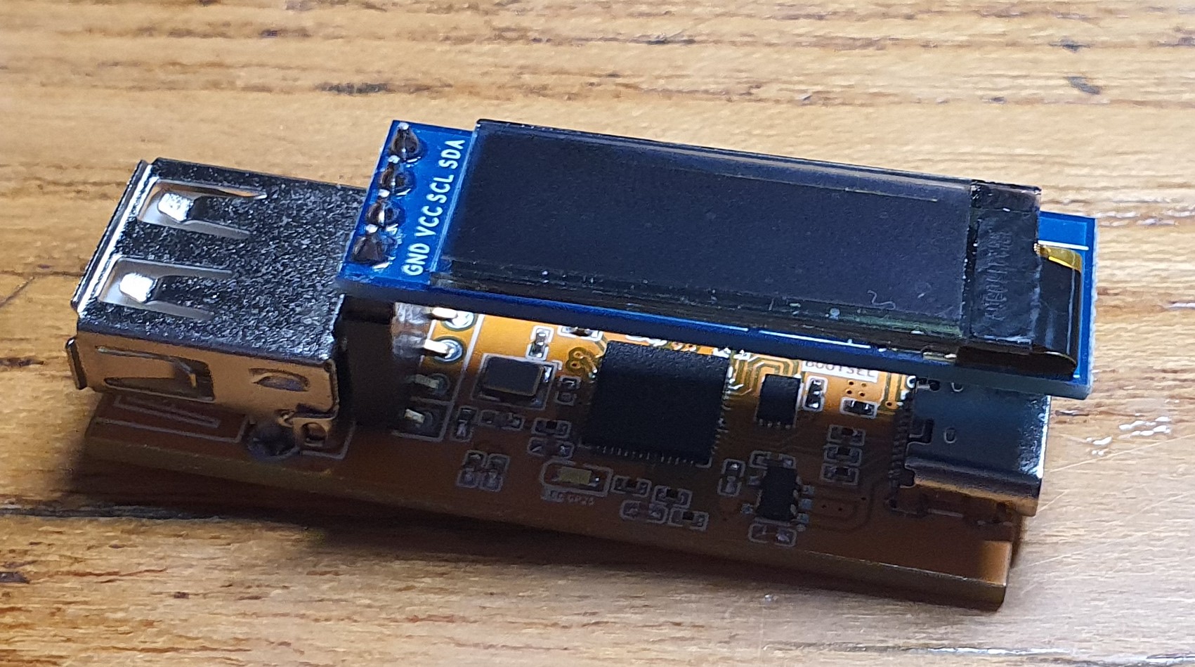
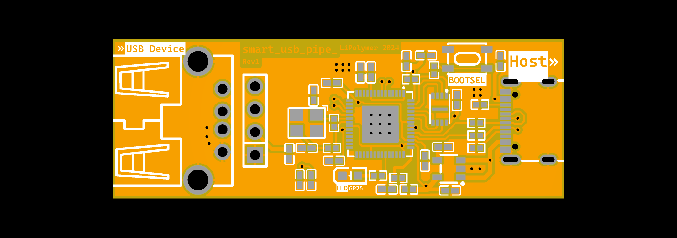
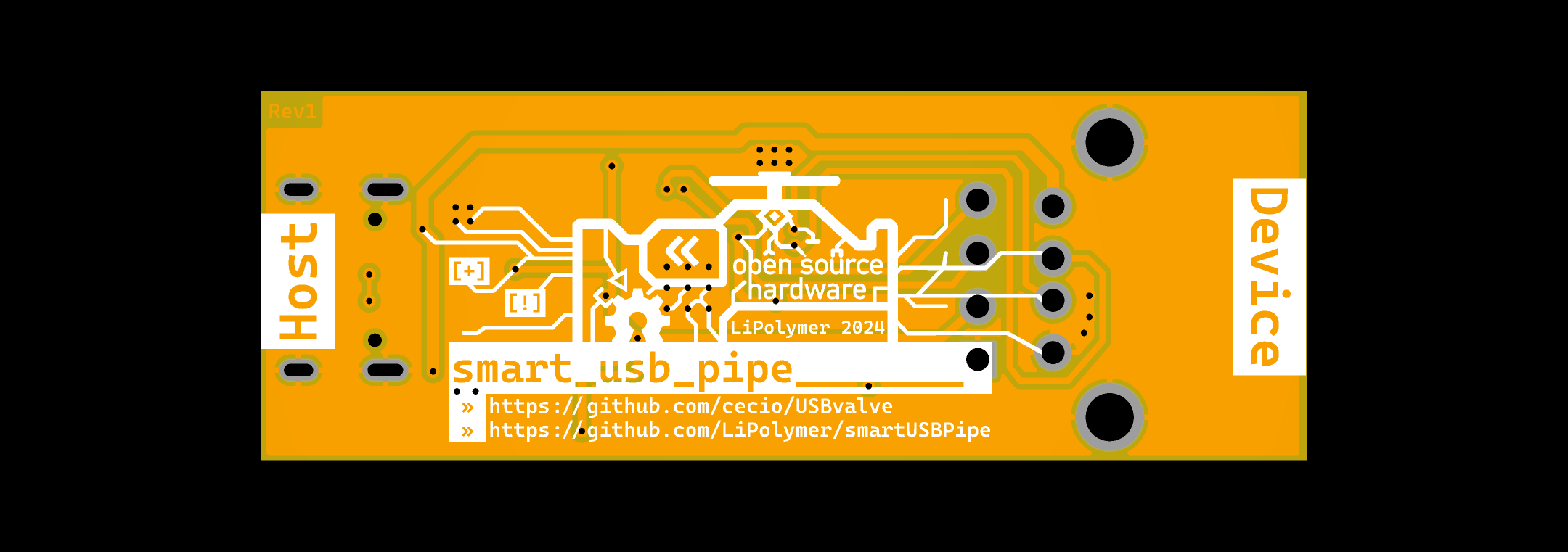
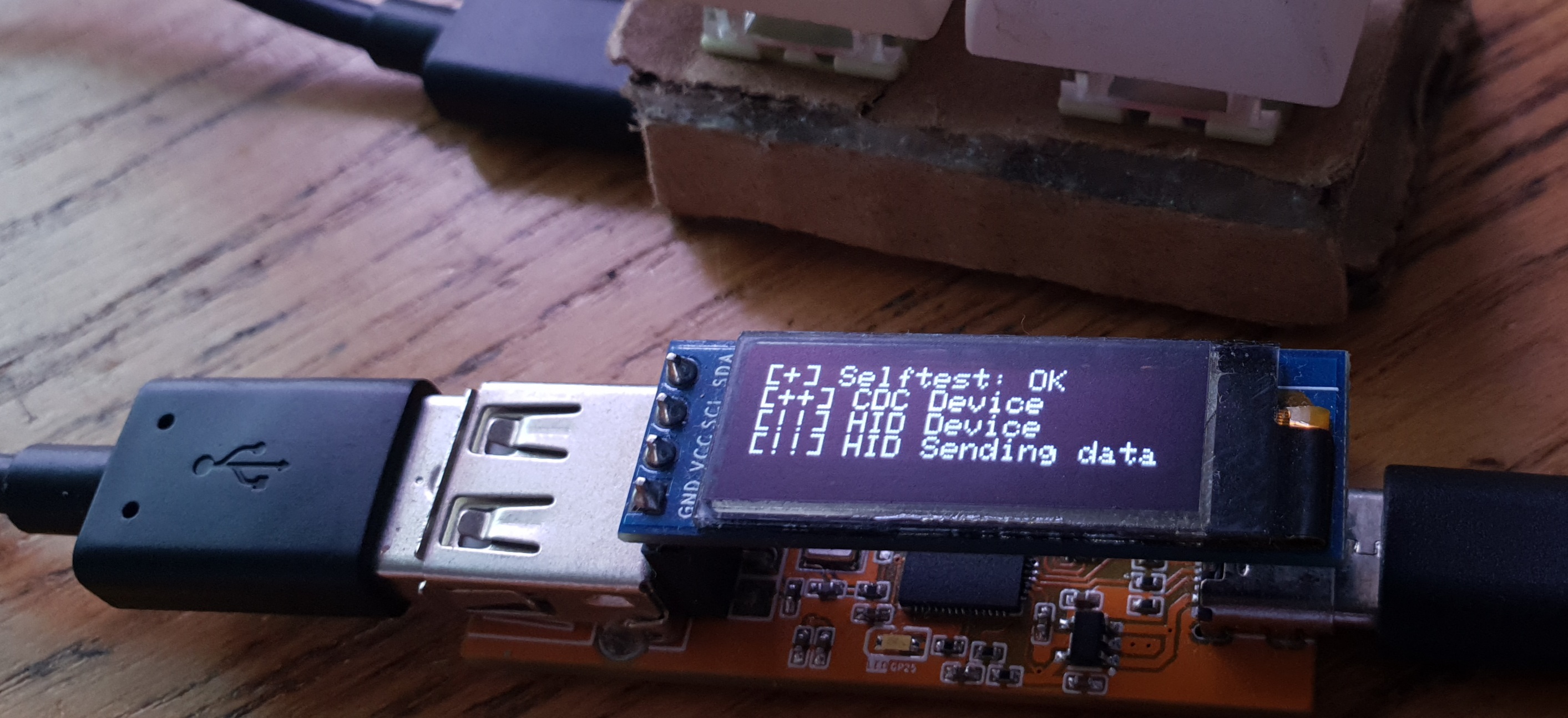 [USBpipe](https://github.com/LiPolymer/smartUSBPipe) is a dedicated PCB for this project.
You can find everything you need in `./PCB/USBpipe/` folder.
[USBpipe](https://github.com/LiPolymer/smartUSBPipe) is a dedicated PCB for this project.
You can find everything you need in `./PCB/USBpipe/` folder.
 ### Flash Firmware
To flash the firmware, follow these steps:
- Connect the Raspberry Pi Pico with the USB cable, by keeping the *BOOTSEL* button pressed (the big white button on the board)
- release the button
- you will see a new drive on the system, named `RPI-RP2` (in Linux envs you may have to manually mount it)
- copy the proper firmware file (with extension `uf2`) in the folder, depending on the OLED you used
- wait few seconds until the mounted folder disappear
It's done!
### Anti-Detection
I don't know if it will ever be the case, but you may want to customize the firmware in order to avoid detection done by *USBvalve-aware* malware :-)
I grouped most of the variables you may want to modify in this section of `usb_config.h` ([see Dockerfile below for rebuilding](https://github.com/cecio/USBvalve#dockerfile))
```C
// USB anti-detection settings
//
// Set USB IDs strings and numbers, to avoid possible detections.
// Remember that you can cusotmize FAKE_DISK_BLOCK_NUM as well
// for the same reason. Also DISK_LABEL in ramdisk.h can be changed.
//
// You can see here for inspiration: https://the-sz.com/products/usbid/
//
// Example:
// 0x0951 0x16D5 VENDORID_STR: Kingston PRODUCTID_STR: DataTraveler
//
#define USB_VENDORID 0x0951
#define USB_PRODUCTID 0x16D5
#define USB_DESCRIPTOR "DataTraveler"
#define USB_MANUF "Kingston"
#define USB_SERIAL "123456789A"
#define USB_VENDORID_STR "Kingston" // Up to 8 chars
#define USB_PRODUCTID_STR "DataTraveler" // Up to 16 chars
#define USB_VERSION_STR "1.0" // Up to 4 chars
```
### Building your firmware
Obviously you can also build your own firmware. To build you need the *Raspberry Pi Pico SDK* and this repoository.
Basic recompile instructions:
```
export PICO_SDK_PATH=
git clone --recursive https://github.com/cecio/USBvalve.git
cd USBvalve
mkdir build && cd build
cmake -DPICO_BOARD=pico .. # or pico2 for standard build
make -j$(nproc)
# Output: build/src/USBvalve.uf2
```
If you want to re-create a new fake filesystem, you may want to have a look to the `utils` folder, where I placed some utilities to build a new one.
#### Dockerfile
If you want to build your own firmware, after you customized it, I provide a `Dockerfile` which builds a complete building environment and compile the firmware.
Enter the following commands in the main `USBvalve` folder to build:
```
# To Build:
# docker build -t usbvalve-sdk -f Dockerfile.sdk .
#
# To Run (default: pico, SSD1306 OLED 128x32):
# docker run --rm -v $PWD:/mnt usbvalve-sdk
#
# Options (via environment variables):
# BOARD=pico|pico2 Board target (default: pico)
# OLED_HEIGHT=32|64 OLED display height (default: 32)
# PIWATCH=1 Use GC9A01 round TFT instead of SSD1306
# USE_BOOTSEL=1 Enable BOOTSEL button (disrupts Low Speed USB)
#
# Examples:
# docker run --rm -e BOARD=pico2 -v $PWD:/mnt usbvalve-sdk
# docker run --rm -e PIWATCH=1 -v $PWD:/mnt usbvalve-sdk
# docker run --rm -e BOARD=pico2 -e OLED_HEIGHT=64 -v $PWD:/mnt usbvalve-sdk
```
The firmware will be placed with extension `uf2` in folder `USBvalve_out`.
### Contribute
If you have ideas or improvements in your mind, I encourage you to open an issue so that we can improve the project together! Thanks!
### Support
If you have question or need support you can open an `Issue` here or reach me out on Twitter/X [@red5heep](https://twitter.com/red5heep)
### Community versions
The Community created some forks implementing support for other boards, or other modifications. **Thank you to everyone** who contributed to the development of **USBvalve**.
Here below an unofficial/incomplete/unsupported list:
- [USBvalve-tbfa-Mod](https://github.com/TryBreakFixAgain/USBvalve-tbfa-Mod)
## SAFETY WARNING
> [!WARNING]
> I've received a lot of questions about **USBvalve** and *USB killer devices*. **USBvalve** is not built to test these devices, it has not any kind of insulation or protection, so if you have the suspect you are dealing with one of these devices, test it with something else, NOT with **USBvalve** or you may damage the device, yourself or objects near to you.
### Flash Firmware
To flash the firmware, follow these steps:
- Connect the Raspberry Pi Pico with the USB cable, by keeping the *BOOTSEL* button pressed (the big white button on the board)
- release the button
- you will see a new drive on the system, named `RPI-RP2` (in Linux envs you may have to manually mount it)
- copy the proper firmware file (with extension `uf2`) in the folder, depending on the OLED you used
- wait few seconds until the mounted folder disappear
It's done!
### Anti-Detection
I don't know if it will ever be the case, but you may want to customize the firmware in order to avoid detection done by *USBvalve-aware* malware :-)
I grouped most of the variables you may want to modify in this section of `usb_config.h` ([see Dockerfile below for rebuilding](https://github.com/cecio/USBvalve#dockerfile))
```C
// USB anti-detection settings
//
// Set USB IDs strings and numbers, to avoid possible detections.
// Remember that you can cusotmize FAKE_DISK_BLOCK_NUM as well
// for the same reason. Also DISK_LABEL in ramdisk.h can be changed.
//
// You can see here for inspiration: https://the-sz.com/products/usbid/
//
// Example:
// 0x0951 0x16D5 VENDORID_STR: Kingston PRODUCTID_STR: DataTraveler
//
#define USB_VENDORID 0x0951
#define USB_PRODUCTID 0x16D5
#define USB_DESCRIPTOR "DataTraveler"
#define USB_MANUF "Kingston"
#define USB_SERIAL "123456789A"
#define USB_VENDORID_STR "Kingston" // Up to 8 chars
#define USB_PRODUCTID_STR "DataTraveler" // Up to 16 chars
#define USB_VERSION_STR "1.0" // Up to 4 chars
```
### Building your firmware
Obviously you can also build your own firmware. To build you need the *Raspberry Pi Pico SDK* and this repoository.
Basic recompile instructions:
```
export PICO_SDK_PATH=
git clone --recursive https://github.com/cecio/USBvalve.git
cd USBvalve
mkdir build && cd build
cmake -DPICO_BOARD=pico .. # or pico2 for standard build
make -j$(nproc)
# Output: build/src/USBvalve.uf2
```
If you want to re-create a new fake filesystem, you may want to have a look to the `utils` folder, where I placed some utilities to build a new one.
#### Dockerfile
If you want to build your own firmware, after you customized it, I provide a `Dockerfile` which builds a complete building environment and compile the firmware.
Enter the following commands in the main `USBvalve` folder to build:
```
# To Build:
# docker build -t usbvalve-sdk -f Dockerfile.sdk .
#
# To Run (default: pico, SSD1306 OLED 128x32):
# docker run --rm -v $PWD:/mnt usbvalve-sdk
#
# Options (via environment variables):
# BOARD=pico|pico2 Board target (default: pico)
# OLED_HEIGHT=32|64 OLED display height (default: 32)
# PIWATCH=1 Use GC9A01 round TFT instead of SSD1306
# USE_BOOTSEL=1 Enable BOOTSEL button (disrupts Low Speed USB)
#
# Examples:
# docker run --rm -e BOARD=pico2 -v $PWD:/mnt usbvalve-sdk
# docker run --rm -e PIWATCH=1 -v $PWD:/mnt usbvalve-sdk
# docker run --rm -e BOARD=pico2 -e OLED_HEIGHT=64 -v $PWD:/mnt usbvalve-sdk
```
The firmware will be placed with extension `uf2` in folder `USBvalve_out`.
### Contribute
If you have ideas or improvements in your mind, I encourage you to open an issue so that we can improve the project together! Thanks!
### Support
If you have question or need support you can open an `Issue` here or reach me out on Twitter/X [@red5heep](https://twitter.com/red5heep)
### Community versions
The Community created some forks implementing support for other boards, or other modifications. **Thank you to everyone** who contributed to the development of **USBvalve**.
Here below an unofficial/incomplete/unsupported list:
- [USBvalve-tbfa-Mod](https://github.com/TryBreakFixAgain/USBvalve-tbfa-Mod)
## SAFETY WARNING
> [!WARNING]
> I've received a lot of questions about **USBvalve** and *USB killer devices*. **USBvalve** is not built to test these devices, it has not any kind of insulation or protection, so if you have the suspect you are dealing with one of these devices, test it with something else, NOT with **USBvalve** or you may damage the device, yourself or objects near to you.